HC-05 Bluetooth Module Guide
Posted by Jack L on
The HC-05 Bluetooth module (and related modules) is a very popular module for wireless communication due to its price and capabilities.
In this article, we’ll talk about how to wire and setup the module for operation with an Arduino board.
Wiring
Most HC-05 modules require a 5V operating voltage. However, the TX/RX pins work at 3.3V.
Although most modules have on-board current limiting circuit which allows the TX/RX pins to work with 5V signal, a 5V to 3.3V circuit (a simple voltage divider) at the Arduino TX pin is recommended.
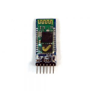
There are a few version of the HC-05 module in the market but for this article, we’ll work with HC-05 Bluetooth module, the one we carry in our shop.
PARTS
- HC-05 Bluetooth module (Bluetooth over serial)
- Arduino Uno R3 or Arduino Uno R3 SMD
- Breadboard
- Jumper wires
- Arduino IDE
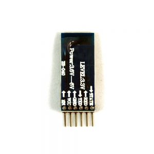
WIRING GUIDE
- HC-05 GND — Arduino GND Pin
- HC-05 VCC (5V) — Arduino 5V
- HC-05 TX — Arduino Pin 10 (soft RX)
- HC-05 RX — Arduino Pin 9 (soft TX)


Programming
The default setting of the HC-05 is suitable for most cases. However, if you want to change some of the setting such as increase the baud rate for higher speed data, you’ll need to enter HC-05’s command mode. Some HC-05 modules have a command pin built onto the board, the one we carry in our shop use a button to enter command mode instead.
To enter command mode, power off the HC-05 module, hold the command mode button (or pull pin 34 high if the HC-05 module doesn’t have a AT button), then power the HC-05 module back on. Once you are in command mode, the module’s LED led will blink at about 2 seconds interval.

Now that your HC-05 is in command mode (also known as AT mode), you can use the Arduino sketch below to program your Bluetooth module.
#include <SoftwareSerial.h>

const int txPin = 9;
const int rxPin = 10;

SoftwareSerial BTSerial(rxPin, txPin); // RX, TX

void setup() {
  Serial.begin(9600);
  Serial.println("Enter AT commands:");
  BTSerial.begin(38400);
}

void loop() {
  if (BTSerial.available())
    Serial.write(BTSerial.read());
  if (Serial.available())
    BTSerial.write(Serial.read());
}
HC-05’s AT mode baud rate is fixed at 38400, however, the BT communication baud rate can be changed from the default 9600 to as fast as 115200 (or faster, but we never tested).
Here is a document explaining the HC-05’s AT command.
Example
- Once you uploaded the sketch onto your Arduino, open the serial monitor at 9600 baud rate, select CR+NL, and you should be able to send AT commands to the HC-05.
- Every time you transmit “AT” (without the quotes), the HC-05 should reply with “OK”
- To check your HC-05’s version, enter “AT+VERSION”
- To change the name of the module, enter “AT+NAME=MYBTNAME”
- To check the current password, enter “AT+PSWD”
- To change the password, enter “AT+PSWD=2345”
- To check the current baud rate, enter “AT+UART”
- To change the BT baud rate to 115200, 1 stop bit, 0 parity, enter “AT+UART=115200,1,0”