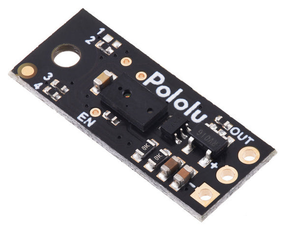


This small lidar-based distance sensor reports the distance of objects up to about 50 cm (20″) away with a pulsed signal similar to a hobby servo control signal. A digital microcontroller pin can be used to time the length of each high pulse, which encodes the measured distance. The sensor works over an input voltage range of 3.0 V to 5.5 V, and the 0.1″ pin spacing makes it easy to use with standard solderless breadboards and 0.1″ perfboards.
Note: The maximum range of 50 cm is only achievable for high-reflectance objects in good ambient conditions. Lower-reflectivity targets or poor ambient conditions will reduce the maximum range.
Overview
This compact sensor makes it possible to measure the distance of objects up to about 50 cm (20″) away using a simple digital pulse width interface (similar to a hobby servo control signal). It uses a short-range lidar module to precisely measure how long it takes for emitted pulses of infrared, eye-safe laser light to reach the nearest object and be reflected back, allowing for 3 mm resolution. As long as the sensor is enabled, it takes continuous distance measurements and encodes the ranges as the widths of high pulses, which can then be timed by a microcontroller using a single digital input.
 |
 |
|
A camera with no IR filter shows the infrared light emitted by a Pololu Digital Distance Sensor. |
|---|
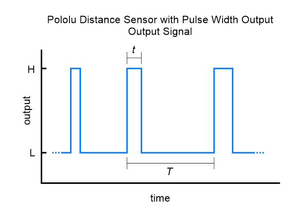
The relationship between measured distance d (in mm) and pulse width t (in µs) is as follows:
The timing uncertainty is approximately ±5%. As objects approach the sensor, the output pulse width will approach 1.0 ms, while an object detected at 50 cm will produce a 1.667 ms pulse width. The sensor uses a pulse width of 2.0 ms to indicate no detection. The pulse period T ranges from around 9 ms to 20 ms, depending on the proximity of the detected object.
The maximum detection range depends on object reflectivity and ambient lighting conditions. In our tests, the sensor was able to reliably detect a white sheet of paper out to around 50 cm away, and it could reliably detect a hand out to around 30 cm away. The following graph shows the measured distances of five units versus their actual distances from a white paper target at several different ranges:
 |
Please note that while this sensor can detect objects almost all the way up to the sensor face, the effective minimum distance it can measure is around 1 cm, so objects closer than 1 cm might still result in a measured distance of around 1 cm.
Specifications
 |
- Operating voltage: 3.0 V to 5.5 V
- Current consumption: 30 mA (typical) when enabled, 0.4 mA when disabled
- Maximum range: approximately 50 cm (20″) (for high-reflectivity targets in good ambient conditions; lower-reflectivity targets or poor ambient conditions will reduce the maximum detection range)
- Update rate: 50 Hz to 110 Hz (20 ms to 9 ms period)
- Field of view (FOV): 15° typical; can vary with object reflectance and ambient conditions
- Output type: digital pulse width
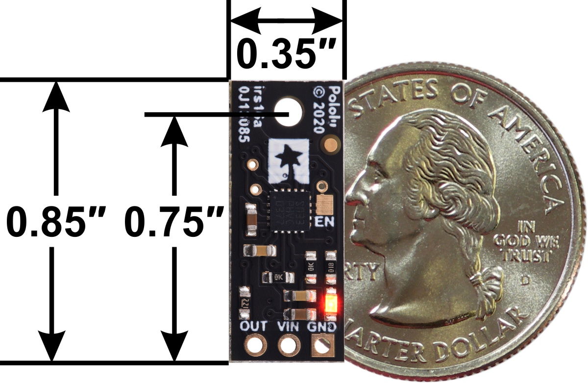
- Dimensions: 0.85″ × 0.35″ × 0.122″ (21.6 × 8.9 × 3.1 mm); see the dimension diagram (192k pdf) for more information
- Weight: 0.014 oz (0.4 g)
Using the sensor
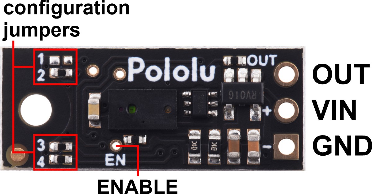 |
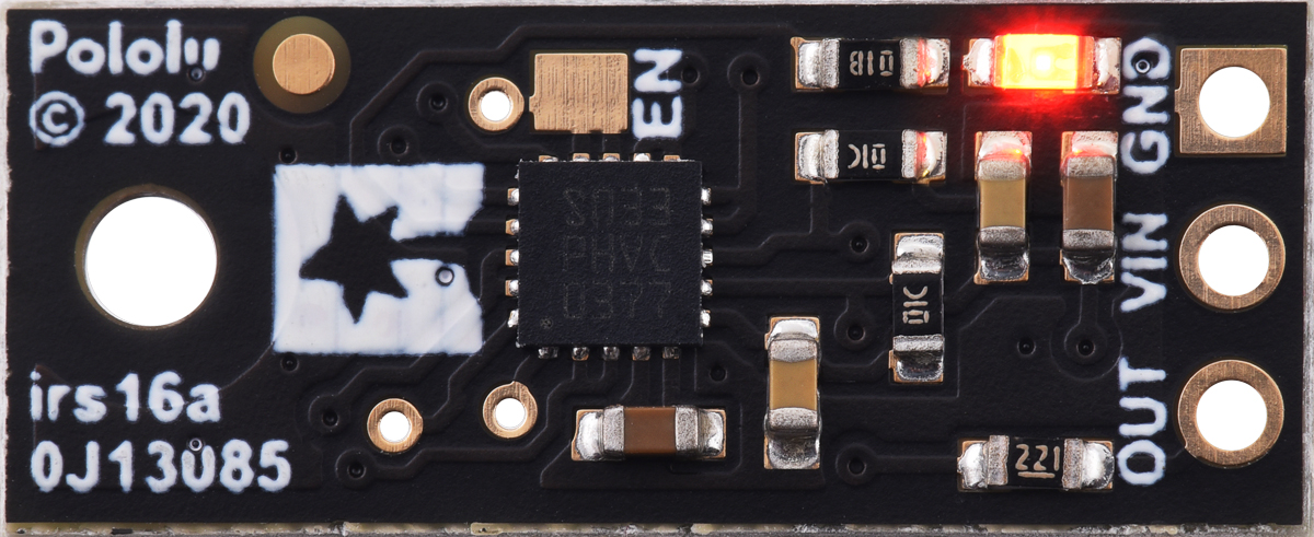
Three connections are necessary to use this module: VIN, GND, and OUT. These pins are accessible through a row of 0.1″-pitch through holes, which work with standard 0.1″ (2.54 mm) male headers and 0.1″ female headers. The VIN pin should be connected to a 3 V to 5.5 V source, and GND should be connected to 0 volts. The sensor outputs its digital pulses on the OUT pin. The low level of the pulses is 0 V, and the high level is VIN. A red LED on the back side of the board also lights whenever an object is detected (the closer the object, the brighter the LED).
|
|
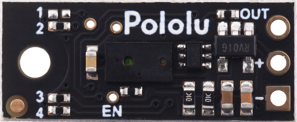
The board has an optional ENABLE pin that can be driven low to put it into a low-power state that consumes approximately 0.4 mA. This pin can be accessed through a via or its neighboring surface-mount pad on the back side labeled “EN” on the silkscreen. The ENABLE pin is pulled up to VIN, enabling the sensor by default.
The board features four surface-mount configuration jumpers that determine its operation mode. Different versions of the Pololu Digital Distance sensors ship with the appropriate jumpers pre-populated with 0 Ω resistors. These resistors can be desoldered from the populated spots or solder bridges can be added across the unpopulated spots to convert one sensor version into another. The table in the section below shows the jumper settings for the different versions.
The board has one mounting hole intended for use with #2 or M2 screws.
The Pololu Digital Distance Sensor family
We have several different versions of Pololu Digital Distance Sensors, all with the same dimensions and pinout:
| Output type | Sensor | Maximum range |
Minimum update rate |
Jumper settings (4321) |
|---|---|---|---|---|
|
digital (does not provide distance measurement) |
Digital output, 5cm | 5 cm | 145 Hz | 0000 |
| Digital output, 10cm | 10 cm | 115 Hz | 0010 | |
| Digital output, 15cm | 15 cm | 95 Hz | 0100 | |
|
pulse width (provides distance measurement) |
Pulse width output, 50cm max | 50 cm | 50 Hz | 1110 |
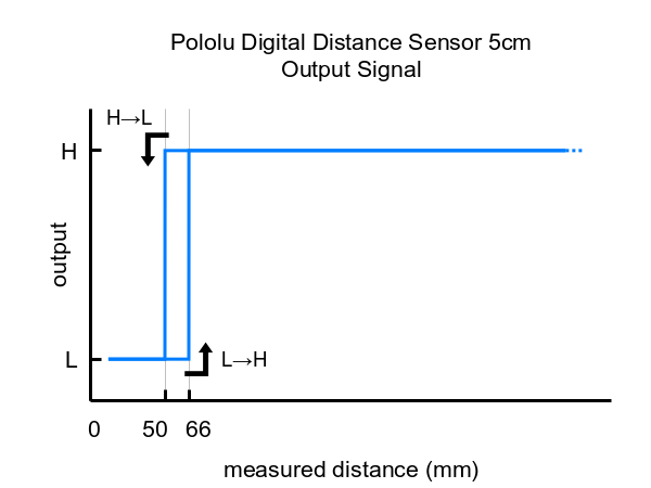
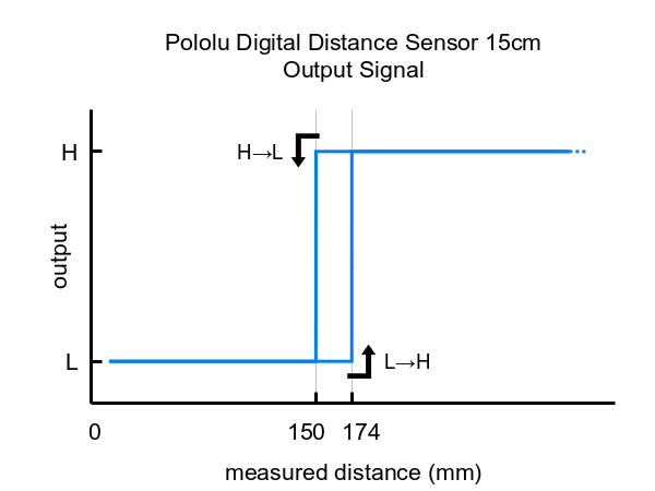
These are the output graphs for the three digital output versions that just report if an object is in their detection range:
|
|
|

The output graph is a bit different for the version that uses a pulse width to encode the measured distance (item #2668). The output for this version is similar to hobby servo control signals and is shown below as a function of time:
|
Dimensions
| Size: | 0.85″ × 0.35″ × 0.122″ |
|---|---|
| Weight: | 0.4 g |
General specifications
| Maximum range: | 5 cm |
|---|---|
| Sampling rate: | 145 Hz1 |
| Minimum operating voltage: | 3.0 V |
| Maximum operating voltage: | 5.5 V |
| Supply current: | 30 mA2 |
| Output type: | digital3 |
Identifying markings
| PCB dev codes: | irs16a |
|---|---|
| Other PCB markings: | 0J13085 |