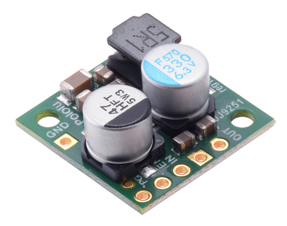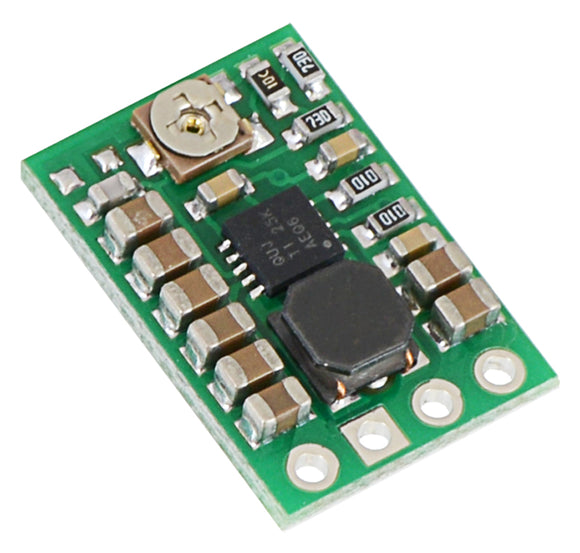

This powerful synchronous switching boost regulator efficiently generates a finely adjustable output voltage between 4.5 V to 20 V from an input voltage as low as 2.9 V while using an input current as high as 8 A. This regulator features reverse voltage protection, and unlike most boost regulators, it offers a true shutdown option that turns off power to the load.
Features and specifications
- Input voltage: 2.9 V to VOUT
- Output voltage: 4.5 V to 20 V (precision-adjustable using built-in 12-turn potentiometer)
- True shutdown option turns off power to the load
- Typical efficiency of 80% to 95%, depending on input voltage, output voltage, and load (see the Typical efficiencies and output currents section below for performance graphs)
- 10 A switch allows for:
- Instantaneous input currents up to 10 A
- Input currents up to 8 A for several seconds
- Input currents around 6 A to 7 A for prolonged durations, depending on input voltage and output voltage
- low quiescent current for most combinations of input and output voltages (but it rises significantly boosting from under 3.5 V to over 13 V)
- Integrated protections:
- Reverse voltage protection
- Short-circuit protection with hiccup recovery
- Over-temperature shutoff
- Under-voltage lockout (typical thresholds are 2.4 V falling, 2.8 V rising)
- Cycle-by-cycle input current limiting to 10 A
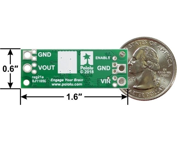
- Compact size: 1.6″ × 0.6″ × 0.22″ (40.6 × 15.2 × 5.5 mm)
- Weight: 3.9 g
- Two mounting holes for #2 or M2 screws
- Smaller holes for 0.1″ header pins and larger holes for terminal blocks offer several options for connecting to the board
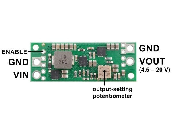
U3V70A connections
 |
The input voltage, VIN, must be at least 2.9 V and should not exceed the output voltage, VOUT. (If VIN is higher than VOUT, the higher input voltage will show up on the output, which is potentially dangerous for your connected load and could also damage the regulator.)
The regulator is enabled by default: a 100 kΩ pull-up resistor on the board connects the ENABLE pin to reverse-protected VIN. The ENABLE pin can be driven low (under 0.4 V) to turn off power to the load and put the board into a low-power state. The quiescent current draw in this sleep mode is dominated by the current in the pull-up resistor from ENABLE to VIN, which will draw 10 µA per volt on VIN when ENABLE is held low, and by the reverse-protection circuit, which draws current when VIN exceeds 7 V. The current draw of the reverse-protection circuit is independent of the state of ENABLE and is given by (VIN – 7 V)/100 kΩ.
Setting the output voltage
 |
The output voltage of the regulator is controlled with a 12-turn precision potentiometer. Turning the potentiometer clockwise increases the output voltage, and it can be measured using a multimeter.
 |
|
Output voltage settings for the 4.5-20V Fine-Adjust Step-Up Voltage Regulator U3V70A. |
|---|
Please note that the output voltage can be set below 4.5 V at the low end and above 20 V at the high end. While this should not damage the regulator, the regulator might not work reliably or its output could become unstable when the output voltage is not within the recommended 4.5 V to 20 V range.
Warning: You should be careful not to use an input voltage that exceeds the output voltage setting, so we recommend setting the output voltage with an input voltage that is below 4 V. We do not ship these with any particular default output voltage setting.
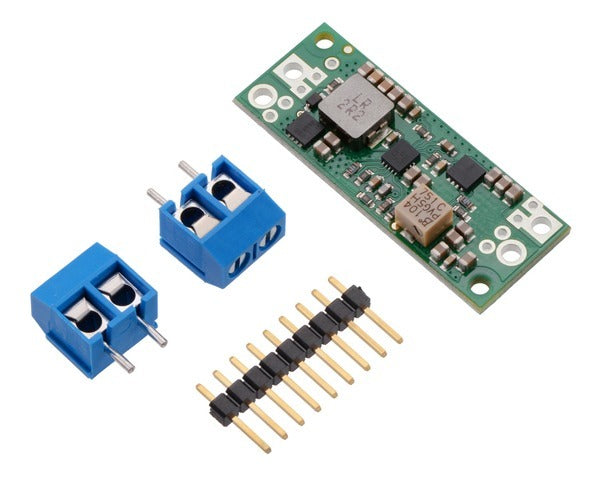
Included hardware
|
|

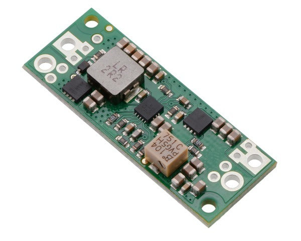
This regulator offers several options for making electrical connections. The nine smaller through-holes on the ends of the board are arranged with a 0.1″ spacing for compatibility with solderless breadboards, connectors, and other prototyping arrangements that use a 0.1″ grid. The included 0.1″ male header can be broken or cut into smaller pieces as desired and soldered into these smaller through-holes. Alternatively, the included terminal blocks can be soldered into the larger holes to allow for convenient temporary connections of unterminated wires. You can also solder wires directly to the board for the most compact installation.
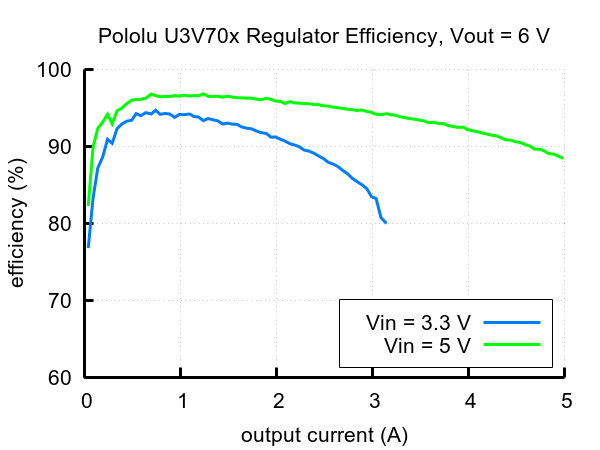
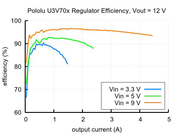
Typical efficiencies and maximum output currents
The efficiency of a voltage regulator, defined as (Power out)/(Power in), is an important measure of its performance, especially when battery life or heat are concerns. As shown in the graphs below, the U3V70x regulators have an efficiency of 80% to 95% for most combinations of input voltage, output voltage, and load.
 |
 |
 |
 |
 |
 |
The maximum achievable output current is approximately proportional to the ratio of the input voltage to the output voltage. Additionally, the maximum output current can depend on other factors, including the ambient temperature, air flow, and heat sinking. The graph below shows the typical maximum continuous output currents these regulators can deliver at room temperature with no forced airflow or heat sinking.
 |
 |
|
Typical maximum quiescent current of Step-Up Voltage Regulator U3V70x (regulator enabled, no load). |
|---|
During normal operation, this product can get hot enough to burn you. Take care when handling this product or other components connected to it.
LC Voltage Spikes
When connecting voltage to electronic circuits, the initial rush of current can cause damaging voltage spikes that are much higher than the input voltage. In our tests with this family of regulator connected with typical power leads (~30″ test clips), we found that input voltages above 17 V caused voltage spikes in excess of 20 V, which could damage the regulator. Lower input voltages caused smaller spikes that could still be problematic for boost regulators operating with the input voltage close to the set output voltage, since input voltages above the set output voltage will propagate to the output and could damage circuits being powered by the regulator. A large electrolytic capacitor (33 μF is a good starting point) can be added close to the regulator between VIN and GND to help suppress these spikes.
Dimensions
| Size: | 0.6″ × 1.6″ × 0.22″1 |
|---|---|
| Weight: | 3.9 g2 |
General specifications
| Minimum operating voltage: | 2.9 V |
|---|---|
| Maximum operating voltage: | 20 V3 |
| Maximum input current: | 10 A4 |
| Minimum output voltage: | 4.5 V5 |
| Maximum output voltage: | 20 V5 |
| Reverse voltage protection?: | Y |
| Output type: | adjustable 4.5-20V5 |
Identifying markings
| PCB dev codes: | reg21a |
|---|---|
| Other PCB markings: | 0J11050, blank white box |
Notes:
- 1. Without included optional headers or terminal blocks. Height with terminal blocks installed is approximately 0.5″.
- 2. Without included optional headers or terminal blocks. Terminal blocks add 3.4 g.
- 3. The operating voltage should not exceed the set output voltage, VOUT.
- 4. Instantaneous. This is the rating for the switch, and regulator actively limits input current to this. Sustainable input current depends on input and output voltage and external conditions like ambient temperature and airflow.
- 5. Output voltage is set by a built-in precision 12-turn potentiometer.