


This item is archived from our catalog and no longer for sale. This page is available as a reference only.
Stepper Motor with 18cm Lead Screw (Bipolar, 200 Steps/Rev, 42x38mm, 2.8V, 1.7 A/Phase)
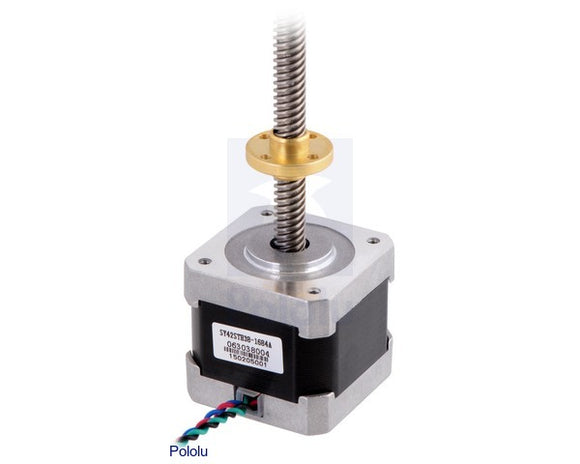
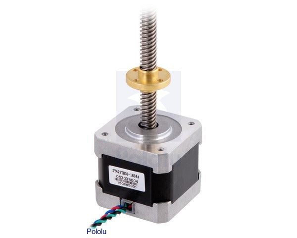
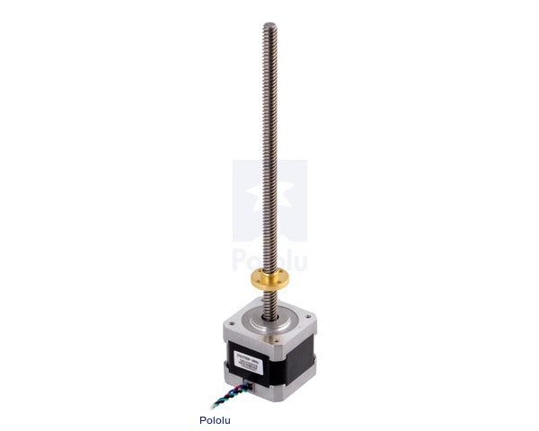
This NEMA 17-size hybrid bipolar stepping motor has an integrated 18 cm (7″) threaded rod as its output shaft, turning it into a linear actuator capable of precision open-loop positioning. The included traveling nut has four mounting holes and moves 40 µm (1.6 mil) per full step; finer resolution can be achieved with microstepping. The stepper motor has a 1.8° step angle (200 steps/revolution) and each phase draws 1.7 A at 2.8 V, allowing for a holding torque of 3.7 kg-cm (51 oz-in).
Overview
This linear positioning drive consists of our 42×38 mm NEMA17 stepper motor with a built-in lead screw in place of the normal output shaft, which makes it easy to move an object or platform in a linear motion with the precision of a stepper motor. Motors like this are especially popular for use in home-built 3D printers (e.g. RepRap) and CNC machines. The stainless steel threaded rod extends from the face of the stepper motor, and since it is integrated into the motor itself, you do not have to deal with bulky shaft couplers or loose set screws.
The included copper alloy traveling nut (also known as a carriage nut) features a mounting flange with four holes threaded for M3 screws. The nut moves 8.0 mm per full revolution of the lead screw, which allows for a linear resolution of 0.040 mm per full step of the stepper motor. Even smaller step sizes can be achieved through microstepping, which is a feature of many bipolar stepper motor drivers. We recommend the MP6500 stepper motor driver carrier or AMIS-30543 stepper motor driver carrier for use with this stepper motor, the latter of which allows for a linear resolution of 1.25 µm per 1/32 microstep. However, please note that the nut is not spring loaded, so changes in direction will result in loss of positioning precision due to backlash.
The maximum achievable linear speed depends a lot on the details of the system, including the load and motor supply voltage.
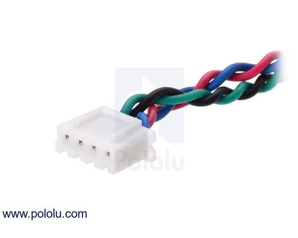
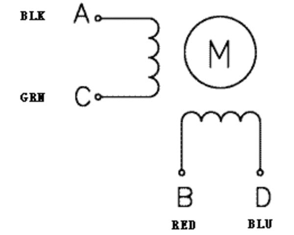
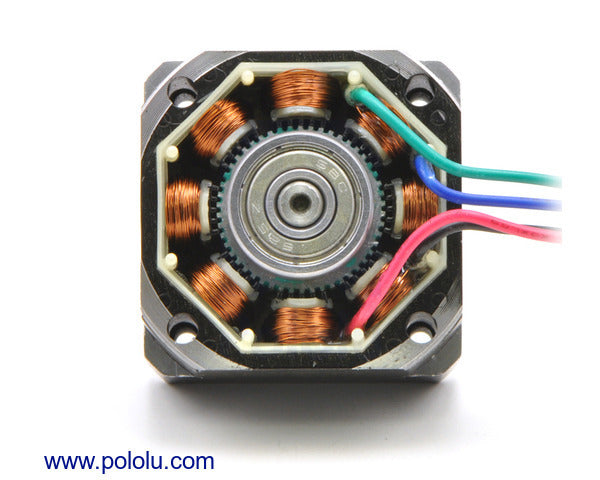
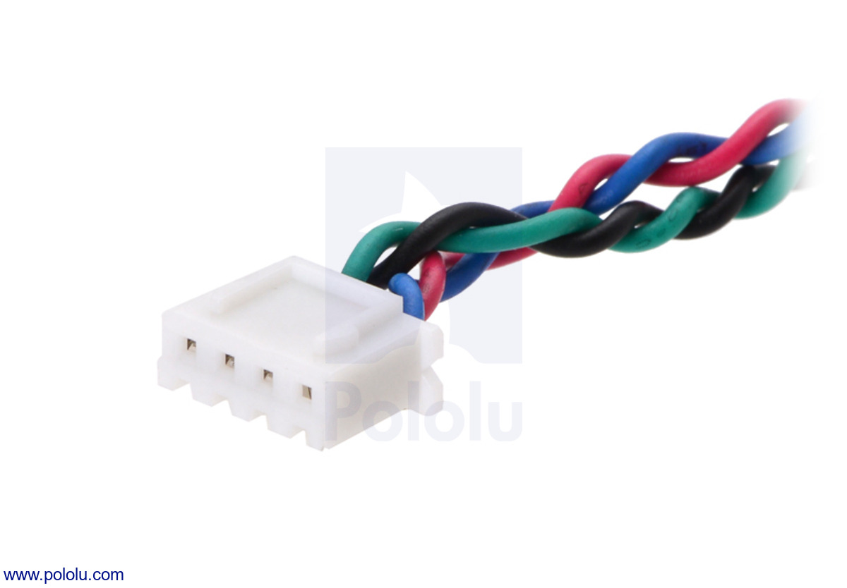
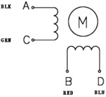
The stepper motor has a 1.8° step angle (200 steps/revolution) and each phase draws 1.7 A at 2.8 V, allowing for a holding torque of 3.7 kg-cm (51 oz-in). The motor has four color-coded wires terminated with a JST XHP-4 connector with 0.1" spacing: black and green connect to one coil; red and blue connect to the other. It can be controlled by a pair of suitable H-bridges (one for each coil), but we recommend using a bipolar stepper motor driver or one of our Tic Stepper Motor Controllers. In particular, the Tics make control easy because they support six different interfaces (USB, TTL serial, I²C, RC, analog voltages, and quadrature encoder) and are configurable over USB with our free configuration utility.
|
|
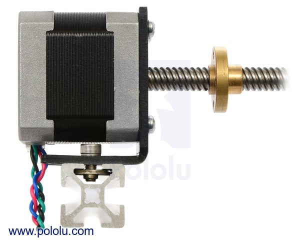
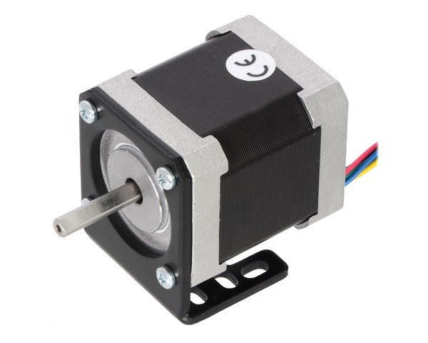
Our NEMA 17 aluminum bracket offers a variety of options for mounting this stepper motor in your project:
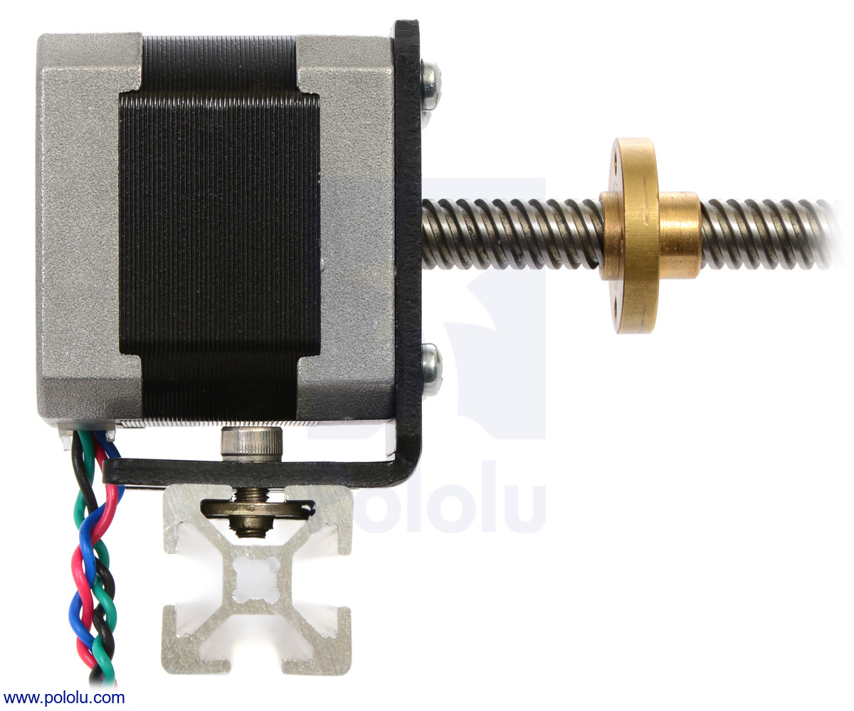 |
| NEMA 17 stepper motor with lead screw mounted with a stamped aluminum L-bracket. |
|---|
Specifications
- Size: 42.3 mm square × 38 mm, not including the shaft (NEMA 17)
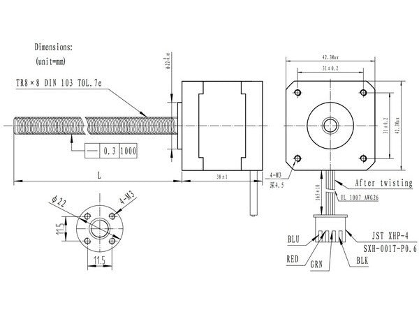
- Leadscrew: Tr 8 × 8(P2)
- Steps per revolution: 200
- Linear step size: 40 µm (1.6 mil) per full step
- Current rating: 1.68 A per coil
- Voltage rating: 2.8 V
- Resistance: 1.65 Ω per coil
- Holding torque: 3.7 kg-cm (51 oz-in)
- Inductance: 3.2 mH per coil
- Lead length: 16 cm (6.5″)
- Output shaft supported by two ball bearings
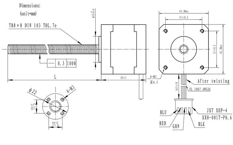
Dimensions
The following diagram shows the stepper motor, lead screw, and traveling nut dimensions in mm. The value of L is 182 mm for the stepper motor with 18cm lead screw. Note that the datasheet incorrectly labels the threaded rod as “TR8×3”; it is really a Tr8×8(P2) leadscrew, which is the ISO designation for a trapezoidal metric thread with an 8 mm nominal diameter, 8 mm lead, and 2 mm pitch. (Put more simply, the rod has four independent threads spaced 2 mm apart, so the carriage nut advances 8 mm for each full revolution of the rod.)
 |